TL;DR: Using Raspberry Pi (as of 2017-04-15):
Using Raspberry Pi 3 Model B v1.2.
https://www.raspberrypi.org/products/raspberry-pi-3-model-b/
I use a 16K Micro SD card. It doesn't have to be the fastest, but reliable is good! It was $10 at Fry's.
I use a ROCCAT Juke external Sound USB Dongle. ( http://www.roccat.org/en-US/Products/Gaming-Sound/Juke/ )
And a 2.5A USB(micro) power plug. (TODO: Measure the current.)
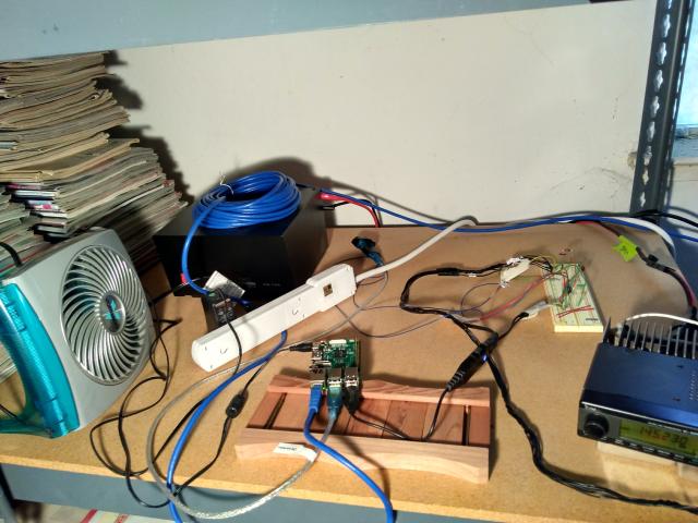
And a small Vornado fan blowing across the Pi and the Mobile 2m rig (Icom 229H).
EchoLink station & notes by W6REK (Henry) on 2017-05-29
Here's a view of the station (click on images for larger size options!)
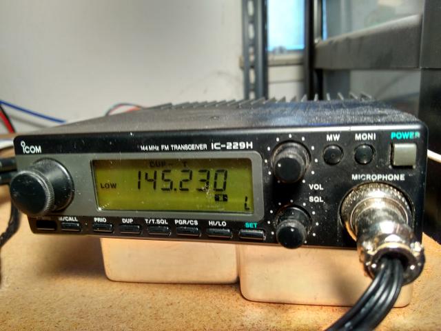
The Icom IC-229H mobile rig (from about 1992) is on the right, tuned to transmit on the repeater's input freuency, with the PL tone, and listen on the repeater's output frequency. It's capable of transmitting with 5W, 10W, 20W, or 50W, but I'm only using 10W. The antenna (not pictured) is a TJB-1 tri-band by Ed Fong ( http://edsantennas.weebly.com/ ) which is hanging in the top of a tree. It seems to have a line-of-sight to the repeater, because we get S7 on the repeater's signal meter with only 10W from San Jose to Palo Alto.
The radio's power supply (black box in back) is an ASTRON RS-12A 12-amp 13.8-volt DC supply ( http://www.hamradio.com/detail.cfm?pid=H0-004423 ). That's much more current than we need -- we probably draw less than 1A when receiving and under 3A when transmitting -- but it's a solid, very reliable supply, and only cost about $20 more than the 5A supply. It's fed AC power via a switch (not pictured) that I can control via the internet, so I can turn off the radio via remote control if I need to.
The small Vornado fan ($20 to $30, I forget, from Fry's) blows over the power supply for the Rasberry Pi, over the Raspberry Pi itself, over the USB Audio dongle, and over the Icom transceiver.
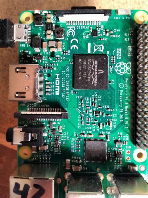
Here's the Raspberry Pi 3 Model B Revision 1.2:
I added a 16GB SD card (solid state "flash" disk). It doesn't need to be fast, but I did get a name brand hoping it would be reliable.
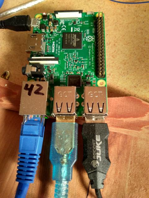
There are 4 connections to the board:
It's powered via a micro USB socket on the back left. It should be at least 2.5A supply, which is more than most adapters provide. If an adapter comes with your Raspberry Pi board, use it.
On the front left, the blue cable is Ethernet. The Pi does have Wifi, and I used it for a while, but using the cable makes it more reliable. We have a /29 network from Comcast that's supposed to be business quality. This gives us 5 usable static public IP addresses, so we give one to the Pi. There is no firewall; we make sure the Pi only runs the minimum services needed.
The middle front is a USB serial dongle. The RTS output pin from it is used for the PTT signal. More about this later. These are easy to order on the internet, for $8 to $10. I got a couple of them; they both use the same chip set as the more expensive cables marketed for Ham Radio.
The right front is a USB Audio dongle. It has two plug holes in the dongle, one for audio in (e.g. microphone input) and one for audio out (e.g. headphones). Fry's has several models. Mine is a ROCCAT Juke ( http://www.roccat.org/en-US/Products/Gaming-Sound/Juke/ ) costing about $15 to $20. I also tried a couple of cheaper USB Audio dongles and they worked, too.
Now here's a closeup of the Icom rig:
This model does not have Tone Squelch on receive, but I haven't had a problem with that.
I made my own cable for an 8-pin DIN plug that fits in the microphone socket. The manual for the IC-229H has the electrical pinout (search the net for the manual PDF).
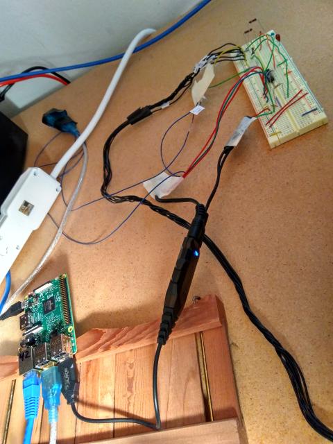
Here you can see my breadboard with 4 sets of wires coming to it:
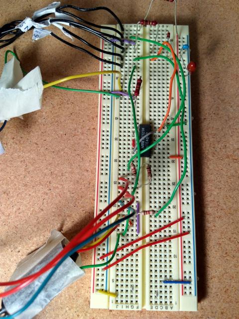
The breadboard contains connetions between those wires, 1Kohm resistors in the audio connections, and a 4049 CMOS hex inverter/buffer chip for the PTT control.
This breadboard is meant to be temporary, but it has been stable so far.
One advantage to the breadboard is you can simulate things going wrong, and make sure there's no problem if various things are out. You especially want to make sure the PTT is not activated if either the Pi is turned off, or while it is booting up, or if power to the 4049 is lost.
The 4049 is powered from a +8V output in the microphone cable, but that +8V is run through a 100 ohm resistor first, so really it's closer to 7V. The inverter is needed because the RS2332 RTS output is active-high, but the radio's PTT input is a typical open-collector active-low input.
Using a CMOS 4049 has a couple of advantages over most other chips. It can handle input voltages outside its power rails well enough that RS232 inputs (which can range like +- 15V) can go directly to an input. Also it is a "buffer", so it can drive higher output current than most TTL or CMOS chips.
I actually use 3 inverters in sequence, so the stress of input and of output are on different inverters, and it sharpens the response as a voltage comparator to voltages near the center of the power rails.
I run its output through a switching diode and a current-limiting 100ohm resistor before connecting it to the PTT input to the radio, and that works fine to pull the signal down to transmit.
Here's my breadboard:
The audio is connected like this:
Both the Left and Right output are each run through a 1K resistor, and then connected to the Radio's microphone input.
The "AF" audio output of the Radio is run through a 1K resistor, and that goes to the monophonic microphone input.
For different radios and different sound cards, obviously, your mileage may vary. I have no idea how much it will vary. I arrived at this design through experimentation.
SvxLink
TODO: Write about SvxLink, changes I made to it, and configuration.
Quick hints: I modified the C++ so that N6NFI's squelch crash doesn't open SvxLink's squelch. My changes are here: https://github.com/strickyak/svxlink
Use "Simplex" Logic rather than "Repeater" Logic.
Comment out all of the messages (like startup & shutdown & connections ) in the Tcl script for the Logic module.
Disable the Roger Beep.
Disable DTMF detection. DTMF tones should just pass through transparently, like any other noise.
I replaced the ID code with code to make the ID in Morse Code. And that's the ONLY thing that my SvxLink will send to the repeater, beyond the voice of people transmitting via EchoLink.
I also increased the gap between Morse Code letters, to make them a bit more readable to non-CW-gurus.
We must use Vox Squelch from the radio to SvxLink, because we want the squelch to close after the repeater's Courtesy Tone, and not to stay open during the possible extra 5 seconds of dead carrier.
I'm using the RTS on an (otherwise unused) USB Serial cable to control the PTT. Most people would probably use a GPIO pin. I haven't had time to experiment with that, but the USB Serial is under $10, works well, is very reliable, and has good properties when the Pi is off or rebooting (you really don't want to activate the PTT inadvertently!).
Thanks to Andy Korsask KR6DD for sharing his suggestions & experience with the EchoLink program. Many of the settings in SvxLink are comparable. But there are also some strong differences, and some things that each supports that the other does not.
Also Massive Thanks to Tobias Blomberg SM0SVX for the svxlink software https://github.com/sm0svx/svxlink and for making it open source! It's beautifully structured, beautifully written C++ code, and the scripting in Tcl has been easy to customize.
TODO: Clean up and publish my configs.
2017-06-06: Without explanation, here is my current hacked-up config: edited-w6rek-r.svxlink.conf.tgz Comments often indicate that I was experimenting.
(On this page there is a picture of an older setup, running Windows 10, using a Logitech dongle: http://wiki.yak.net/1097 )
Notes To Self
SOX:
dd if=/dev/audio of=id7.raw bs=1000 count=24
dd bs=200 if=id7.raw skip=10 count=90 > id77.raw
sox -e mu-law -r 8k -b 8 -c 1 id77.raw id77.wav norm fade h 0.1 2.3 0.1 ; play id77.wav
Stray Files
Crude FFT of N6NFI
Time goes down. The last thing is a BeeBoop. (I made this myself, so it's not polished, and half the horizontal axis is negative frequencies.)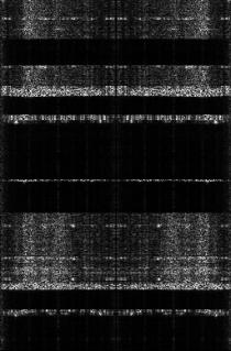
For future use: https://freegeoip.net/
