de W6REK 2019-09-16
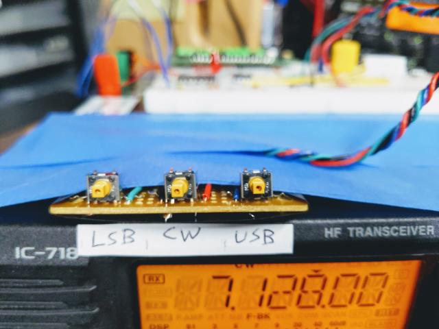
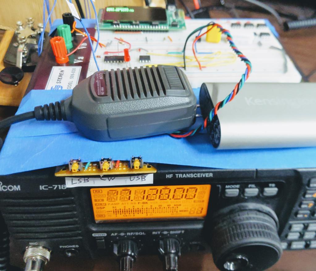
This project adds 3 buttons to my Icom IC-718 rig: LSB, CW, USB.
They not only change the mode of the rig, they also change the RF POWER and the AF volume in the following way:
When you want to use the manual tuner, you want to switch to CW mode, turn the audio volume down, and reduce the RF POWER. Pressing the new CW button does all three. Then you can use the morse code key to activate the transmitter while you frobulate the knobs on the manual tuner (e.g. MFJ-941E). (The volume is turned down so it doesn't make a loud beep when you key down, and the RF POWER is down so you don't burn up the transmitter before you get it tuned.)
Then when you want to talk, you want to switch to Lower Sideband or Upper Sideband, turn the RF POWER back up, and turn the audio volume back up. Hitting the new LSB or USB button does all three.
Later when you QSY or change bands and you want to retune, hit CW again, and repeat.
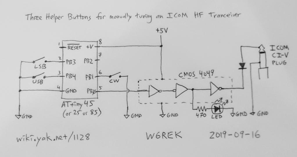
The breadboard contains an 8-pin ATtiny85 processor (just over $1), but an ATtiny45 (under $1) would also work. It's programmed with the code shown below. It watches the three buttons, and when one is pressed, it sends CAT commands to the transceiver to change MODE, RF POWER, and AF level. A 16-pin CMOS 4049 (under $1) buffers the output of the processor, and a switching diode connects it to the bi-directional Open Collector data line in the CI-V interface (using the 3.5mm jack on the back of the transceiver). Although the transceiver responds to each CAT command, the processor doesn't listen. It just delays 100ms so the transceiver has time to respond. The CAT communication is only one-way: the processor is programmed to transmit serial (1200 baud, no parity, 1 stop bit) but not to receive.
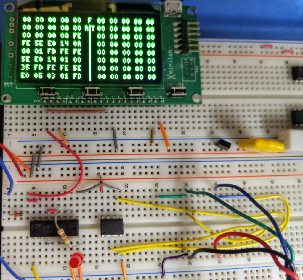
A Gabotronics oscilloscope is also on the breadboard as a protocol decoder. It shows the raw hex bytes sent by the processor and the response from the transceiver. Packets begin with FEFE and end with FD. FB is the "okay" response payload.
With CAT controls on modern radios comes great power. This project demonstrates that if you don't like the user interface provided by your radio, you can often build your own, and use CAT commands to send and receive data from the radio.
The ATtiny C++ code is below, for the Arduino programming environment. With small modifications, you could also run this on an ATmega chip, like an Arduino, and have a lot more inputs and outputs to do more things.
// Manual Tuner Helper for ICOM IC-718 HF Transceiver (for ATtiny{45,85}).
// Use internal 16MHz clock.
// Sends at 1200 Baud, if you calibrate sending 1010101010... to be 600Hz.
// Does not Receive.  The ACK from the radio is ignored.

constexpr bool CALIBRATION_MODE = false;  // Set true for 600 Hz calibration

// In a simple toggle loop, N=1220 creates 600Hz on my Gabotronic Meter.
constexpr unsigned int N = 1220;
constexpr int LED_BUILTIN = 0;
constexpr int EXTRA_STOP_BITS = 2;  // Slow things down a bit, for easier sync.

#define HELLO_718 "\xFE\xFE\x5E\xE0"  /* Radio is 5E.  This controller is E0. */
#define BYE       "\xFD\xFF"  /* FD is to radio; FF is our signal for End Of String */

#define SET_MODE_LSB "\x06\x00\x01"  /* LSB 2800 */
#define SET_MODE_USB "\x06\x01\x01"  /* USB 2800 */
#define SET_MODE_CW  "\x06\x03\x01"  /* CW 2100 */

#define SET_VOLUME_HIGH "\x14\x01\x01\x50"  /* 150 out of 255 */
#define SET_VOLUME_LOW  "\x14\x01\x00\x35"  /* 035 out of 255 */

#define SET_RF_POWER_HIGH "\x14\x0A\x01\x28"  /* 128 out of 255 is 50W */
#define SET_RF_POWER_LOW  "\x14\x0A\x00\x01"  /* 001 out of 255 is  1W */

#define READ_FREQ   "\x03"
#define READ_MODE   "\x04"

// the setup function runs once when you press reset or power the board
void setup() {
  pinMode(LED_BUILTIN, OUTPUT); // LED and inverse of Serial Out
  pinMode(1, INPUT_PULLUP);
  pinMode(2, INPUT_PULLUP);
  pinMode(3, INPUT_PULLUP);
  pinMode(4, INPUT_PULLUP);
}

volatile unsigned int volatile_junk;
void SpinDelay(unsigned int n) {
  unsigned int i;
  for (i=0; i<n; i++) volatile_junk = i;
}

void SendBit(byte low_bit) {
      digitalWrite(LED_BUILTIN, (low_bit & 1) ? LOW : HIGH);
      SpinDelay(N);
}

void CivSend(const byte* s) {
  for (s=s; *s != 0xFF; s++) {
    SendBit(0);  // Start bit.
    byte shift_reg = *s;
    for (byte j = 0; j < 8; j++) {
      SendBit(shift_reg);
      shift_reg >>= 1;
    }
    SendBit(1);  // Stop Bit
    if (!CALIBRATION_MODE) {
      for (int j = 0; j<EXTRA_STOP_BITS; j++) {
        SendBit(1);  // Extra Stop Bits
      }
    }
  }
}

void DoTune() {
    CivSend(HELLO_718 SET_RF_POWER_LOW BYE );
    delay(100);
    CivSend(HELLO_718 SET_VOLUME_LOW BYE );
    delay(100);
    CivSend(HELLO_718 SET_MODE_CW BYE );
    delay(100);
}
void DoLSB() {
    CivSend(HELLO_718 SET_MODE_LSB BYE );
    delay(100);
    CivSend(HELLO_718 SET_RF_POWER_HIGH BYE );
    delay(100);
    CivSend(HELLO_718 SET_VOLUME_HIGH BYE );
    delay(100);
}

void DoUSB() {
    CivSend(HELLO_718 SET_MODE_USB BYE );
    delay(100);
    CivSend(HELLO_718 SET_RF_POWER_HIGH BYE );
    delay(100);
    CivSend(HELLO_718 SET_VOLUME_HIGH BYE );
    delay(100);
}

// InputSwitches returns a bitmask of which switches are pressed.
byte InputSwitches() {
  byte z = 0;
  if (digitalRead(1) == LOW) z |= 1;
  if (digitalRead(2) == LOW) z |= 2;
  if (digitalRead(3) == LOW) z |= 4;
  if (digitalRead(4) == LOW) z |= 8;
  return z;
}

// Command returns a bitmask of switches ONLY when previously no switches were pressed.
byte Command() {
  static byte before = 0;
  byte z = 0;
  byte now = InputSwitches();
  if (now && !before) {
    z = now;
  }
  before = now;
  return z;
}

void CommandLoop() {
  byte c = Command();
  switch (c) {
    case 1: DoTune(); break;
    case 4: DoLSB(); break;
    case 8: DoUSB(); break;
  }
  delay(50);
}

void loop() { CommandLoop(); }

#if 0
// Change loop() to call one of these, for testing:

void CalibrationLoop() {
  // Generate alternating 0 and 1 bits at 1200 Baud,
  // so a frequency meter calls it it 600 Hz.
  // Don't forget to set CALIBRATION_MODE
    // repeat { Start: 0 Data: 10101010 Stop: 1 }
    CivSend("\xAA\xAA\xAA\xAA\xAA\xAA\xAA\xAA\xAA\xAA");
}

void ToggleLsbUsbLoop() {
    CivSend(HELLO_718 SET_MODE_LSB BYE );
    delay(1000);
    CivSend(HELLO_718 READ_MODE BYE );
    delay(3000);
    CivSend(HELLO_718 SET_MODE_USB BYE );
    delay(1000);
    CivSend(HELLO_718 READ_MODE BYE );
    delay(3000);
}
void ReadFreqAndModeLoop() {
    CivSend(HELLO_718 READ_FREQ BYE);
    delay(3000);
    CivSend(HELLO_718 READ_MODE BYE);
    delay(3000);
}
#endif
// FIN
I place that code in the public domain. de W6REK


