JERBOA ATtiny85 Modular Synthesizer
(* See my PhreakNIC talk on YouTube: https://www.youtube.com/watch?v=_DyfvBo0WK0 *)
The idea is to create an Analog Modular Synthesizer using a single ATtiny85 microcontroller for each module.
So although those chips are digital microcontrollers, the signals going in and out of them are analog voltages, like in a real analog synthesizer.
What's a *Modular* synthesizer? It means that it's composed of lots of individual modules, each of which usually does a well-defined, often simple operation. Examples are
Kinds of signals in a Modular Synthesizer
"Patch Anywhere": The goal that any inputs and outputs can be connected any way you want. This lets you abuse the above signal types, wiring the to each other, to achieve weird effects.
My design achieves "patch anywhere" as long as you only use the designated inputs & outputs of each module. (Connecting other things, like shorting +5V to Ground, obviously can cause bad problems.)
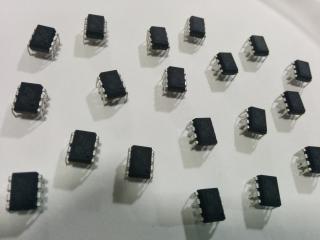
I love the ATtiny85s!
They're $1.20 in single quantities, $100 for a hundred.
8 PIN DIP! Easy to handle, easy to solder, fits in breadboards.
Robust! They're very forgiving of accidental short cirucits and don't require special anti-static handling.
They're the kid brother of the $2 28-pin ATmega328 chip in the Arduino.
Their I/O functions are very similar to, and usually a subset of, the Arudino's capabilities.
The Arduino programming software (and IDE) can be used on Linux, Mac, or Window, to program ATtinies.
The outputs can source or sink enough current to power an LED.
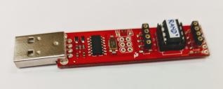
SparkFun sells a $20 programmer for these chips, that uses USB to connect to Linux, Mac, or Windows.
Nice features of the "ATtiny85"
Interlude on debugging
Besides the most basic "turn a LED on or off", debugging features of Jerboa that proved useful:
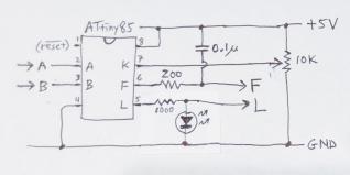
My Standard Jerboa Module
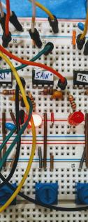
This is my standard Jerboa module. They are all the same except for the programming on the chip.
The chip only has 5 useful I/O pins (the other three are +5V, Ground, and Reset*). So I have to pick and choose which subset of capabilities. I chose 3 analog inputs, 1 analog (PWM) output, and one digital output for the LED.
Here's what I name the signals:
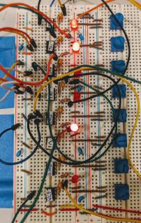
I line the ATtinies down a breadboard in a repeated cell shape. In addition to the chip and connections to ground and +5V power rails, there's two resistors, one capacitor, and an LED in each cell.
Current Demo
  /--> LFO --> LFO --> LFO --\--> PeriodicHold -> VCO --> ECHO --> Speaker
 |                            |
  \                          /
   --------------------------
The three LFOs are just VCOs at low frequencies. Making a loop with these creates chaotic, unpredictable output (thanks to Mark Lentczner for this idea).
On a regualar period, the output of an LFO is sampled and held.
That held sample determines the freqency of the VCO.
The Echo lets you continue to hear the old tone for a short while after a new sample is held. (It has a 450-byte history, where the oldest is averaged with the input, and that average is output and saved at the front of the history.)
Programming a Module
The hardest code has gone into my libraries, mainly "jerboa.h". Writing a module is often very simple.
Where Arduino sketches have "setup()" and "loop()", use a capital letter instead, and the Jerboa runtime will call your routines "Setup()" and "Loop()".
Jerboa provides these inputs:
And you can output with these:
Here is the actual "Sawtooth VCO" module:
#include "/tmp/jerboa/jerboa.h"
#include "/tmp/jerboa/generated-vfo-table.h"

word phase;  // 16-bit phase, 0x0000 to 0xFFFF.

void Setup() {}

void Loop() {
  // Sum all 3 inputs, for a 0-to-15V input:
  word offset = word(InA()) + word(InB()) + word(InK());

  // Look up how much to increment the phase.
  phase += pgm_read_word(VFO_TABLE+offset);

  OutF(phase>>8);  // Analog output of sawtooth wave.

  if (phase & 0x8000) {  // Digital output blinking LED.
    LedOn();
  } else {
    LedOff();
  }
}
The "phase" is a 16-bit unsigned "word". The "VFO_TABLE" was generated by a program in Go. It basically performs the AntiLog function ("2 to the x").
It's configured to know how much to add to the phase for each voltage level, 0V to +15V, since three 5V inputs are added together, InA() InB() & InC().
When the phase overflows, that's a full output wave cycle.
Happy Hacking!
Work in Progress: https://github.com/strickyak/jerboa-attiny85-mod-synth
Notes for the future... ATtiny1616? QFN-20, one external DAC, 16K flash, 2K RAM, $0.80 [jlcpcb]
https://github.com/SpenceKonde/megaTinyCore/blob/master/megaavr/extras/ATtiny_x16.md
https://www.pcbway.com/project/shareproject/ATTiny1616_Minimal_Breakout_board_QFN_bad990fc.html
https://www.adafruit.com/product/5690
https://github.com/SpenceKonde/megaTinyCore
https://github.com/SpenceKonde/AVR-Guidance/blob/master/UPDI/jtag2updi.md
